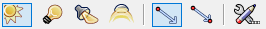
Adding light sources
|
Tool |
Tool set |
Shortcut |
|
Light
|
Visualization |
Shift+Z |

The Light tool places light sources in the drawing. Select the type of light and specify the light preferences.
|
Mode |
Description |
|
Directional Light
|
Projects light with parallel rays, like the sun
|
|
Point Light
|
Radiates light in all directions, like a bare light bulb
|
|
Spot Light
|
Projects light in a specific direction, aimed at a specific object, like a flashlight or conventional spotlight. Spot lights can project a texture in the light beam; see Projecting a texture in a spot light beam.
|
|
Custom Light
|
Defines the source’s emission distribution by a standard intensity distribution profile for accurate physical lighting
|
|
Default Direction
|
For directional lights, click to specify the light position |
|
Set Direction
|
For directional lights, click to set the light direction, and then click to specify the light position |
|
Preferences
|
Sets the preferred light parameters |


Adding a visible light source to a drawing hides the default lighting scheme that is automatically present for basic rendering purposes. The design layer containing the light source must contain 3D geometry upon which to project the light, and the 3D objects must not have a perfectly black fill (which absorbs all light).
Other methods of adding light include the linear light and the area light; see Inserting an area or linear light , and in the Vectorworks Design Suite, the Heliodon tool (see Solar studies).
To add a light source:
Click the tool and select the type of light source to insert (Directional Light, Point Light, Spot Light, or Custom Light). If inserting a directional light, click the light placement mode (Default Direction or Set Direction).
Click Preferences to specify the light source preferences for this session.
For custom lights, the Custom Light Data dialog box opens. For other light types, skip to step 5.
Click Load Distribution and specify the location of the custom light distribution file, and then specify any additional custom light parameters.
Click to show/hide the parameters.Click to show/hide the parameters.
|
Parameter |
Description |
|
Light Rotation Angle |
Specifies the rotation angle of the light source around an axis connecting the light location to the light target; this angle defines the reference plane for the intensity distribution curve |
|
Distribution File |
Displays the distribution file name when a valid distribution file has been selected, or “None” if a valid distribution file has not been designated (click Load Distribution to specify a file) |
|
Load Distribution |
Loads light emission profile data from a standard file. The brightness value is obtained using the integral of the raw emission data provided with the file. The file must be a text file with industry standard intensity distribution data in .ies format. |
|
Distance Falloff |
Select the distance falloff function (rate of intensity change while moving along the beam away from the light source) |
|
Direction |
Specifies the light’s direction by either specifying the light angle or vector |
|
Angle |
Sets the light’s angle by pan and tilt. The pan angle is based on an angle of 0 degrees at the positive Y axis, and is positive in a counter-clockwise direction; the tilt angle is equal to 0 at the horizontal plane, positive when pointing below the plane, and negative when pointing above the plane. |
|
Vector |
Indicates the direction of the light by specifying the coordinates of its X, Y, and Z vectors |
Click OK.
The Light Preferences dialog box opens.
Set the parameters.
Click to show/hide the parameters.Click to show/hide the parameters.
|
Parameter |
Description |
|
On/Off |
Shows or hides the light produced by the light source |
|
Color |
Specifies a color associated with the light source; click the color box to select the color. This parameter is not available if Use Emitter is selected and a Color Temperature is specified. |
|
Cast Shadows |
Creates shadows |
|
Soft Shadows |
Creates more realistic shadows by decreasing hard edges; shadows appear softer the farther they travel, as in reality. Rendering is slower when this option is enabled. |
|
Brightness |
For directional, point, and spot lights, specifies the light source brightness; enter a percentage or drag the slider bar. A value over 100% can be entered. This parameter is not available if Use Emitter is selected. |
|
Dimmer |
Dims the light source brightness (intensity); enter a percentage or drag the slider bar. Only the brightness of the light source is affected; the color temperature is not changed. This parameter is available for custom lights, and for other light types if Use Emitter is not selected. |
|
Use Emitter |
For accuracy, specifies the light’s actual brightness and color temperature; leave deselected to use the light as a simple light source |
|
Get Brightness From |
Specifies the luminous quantity of a light |
|
User Input |
Specifies the brightness as an accurate number in Lux, Lumens, Footcandles, or Candelas; the units vary depending on the light source |
|
Distribution File (custom light only) |
Displays the selected distribution file from the Custom Light Data dialog box; this can be changed by clicking Custom Light Specs |
|
Color Temperature |
Specifies the light color temperature in Kelvin. This refers to an ideal black body emitter, glowing “red hot” or “white hot.” A lower temperature generates an orange color; the hotter the temperature, the closer to white the color of the light is. Specifying this parameter is optional. If not specified, the default temperature is 0, meaning that the final emission color for the light is entirely controlled by the selection in Color. When the temperature is specified, Color cannot be changed. The final emission color is set by the Color Temperature. Color temperature settings can be white-balanced on a per-layer basis; see Setting lighting options. |
|
Directional, Spot, Point, or Custom Light Specs |
Click to set additional specifications for the light source |
Click Directional Light Specs, Spot Light Specs, Point Light Specs, or Custom Light Specs for the selected light source type, to specify additional parameters.
Click to show/hide the parameters.Click to show/hide the parameters.
|
Parameter |
Description |
|
Directional Light |
|
|
Direction |
Specifies the light’s direction by either specifying the light angle or vector |
|
Angle |
Sets the light’s angle by azimuth and elevation. The azimuth angle is set based on an angle of 0 degrees at the negative Y axis, and is positive in a counter-clockwise direction; the elevation angle is the angle above (positive) or below (negative) the horizon. |
|
Vector |
Indicates the direction of the light by specifying the coordinates of its X, Y, and Z vectors |
|
Point Light |
|
|
Distance Falloff |
Select the distance falloff function (rate of intensity change while moving along the beam away from the light source). None: Brightness does not change Smooth: Brightness decreases according to a linear falloff Realistic: Light is brightest near the light source, and falls away according to the square of the distance, as in reality. This falloff selection is the most natural in appearance. |
|
Spot Lights |
|
|
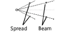
Spread/Beam diagram |
Drag the handles on the diagram to set the spot light Spread and Beam angles, or enter the values in the fields below the diagram
|
|
Spread |
Specifies the spread angle of the spot light (the light cone’s maximum angle) |
|
Beam |
Specifies the beam angle of the spot light (the cone of light that does not change intensity up to the spread angle) |
|
Distance Falloff |
Select the distance falloff function (rate of intensity change while moving along the beam away from the light source). None: Brightness does not change Smooth: Brightness decreases according to a linear falloff Realistic: Light is brightest near the light source, and falls away according to the square of the distance, as in reality. This falloff selection is the most natural in appearance. |
|
Custom Lights |
Opens the Custom Light Data dialog box, to change the parameters entered when first setting up the light, as previously described |
Click OK to return to the Light Preferences dialog box. Click OK to return to the drawing.
Click to place a light object with the parameters specified in the Light Preferences dialog box.
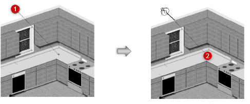
If placing a directional light, click to specify the light position in Default Direction mode. In Set Direction mode, click once to specify the light target or direction, and then click a second time to specify the light position.
Set Direction mode of directional light placement depicted
If placing a spot light, click to place the light, and then drag to specify the light direction and target. The spot light can be aimed at any object. Click again to set the spot light. Use the Look To Height parameter on the Object Info palette to adjust the target Z height precisely.
The spot light target handle and projection line only display when the spot light is selected. Use the Selection tool to move the light. The target handle aims the spot light and can be adjusted with the Selection tool once the spot light has been created. Use the Reshape tool to move the target handle constrained about an axis selected in the Tool bar.
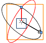
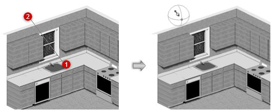
The custom light object is represented by a pair of perpendicular arrow-head vectors and two perpendicular circles. The black vector points to the target location; its axis line (the light axis) connects the light source location to the target. The red vector starts at the light source location, pointing to a reference point on the “equator” of the polar intensity distribution. Also known as the “zero angle line,” it represents the origin for measuring the intensity on the light curve.
The two vectors form the black circle, and the red circle is perpendicular to it. The black circle represents the original plane where the light curves are located. The red circle constrains the movement of the zero angle line.
